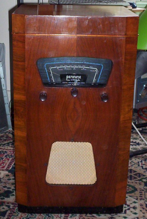
Pennine Amplifiers 'Scout' Radiogram
This had been stashed in the corner of my bedroom for the best part of twenty years. I'd hung onto it in the hope that one day I'd be able to do it up and that hour finally came.
I knew that it worked but not very well so it was probably just a case of duff capacitors.
There doesn't seem to be any data on it but the valves are 6K8GT, ECH35, EBL31 and AZ31.
Some forum ‘experts’ were quick to question the above and one insisted that the 6K8GT must be a substitute and that I should change it for an EF39. If this were the case the wiring would have needed to be changed and there was no sign of interference.
My main concern was the health of the EBL31 as it rattled a large bit of loose metal could be seen within.
After doing the caps it was much better in terms of volume and tone but would only get strong stations. A tweak of the alignment (blind!) soon dealt with that though.
When I was given it I was told it had been bought in 1939. The more I worked on it the less I thought this was correct. For a start two of the valves didn't come on the market 'til 1940 and the wiring on the deck was PVC. I finally settled it when I found that the speaker is dated 27 May 1949.
The idler in the deck was rock hard and had a notch in it. I turned that down and glued a rubber band around it which sorted it out very well. Unfortunately there was some equally past-it rubber in the pick-up.
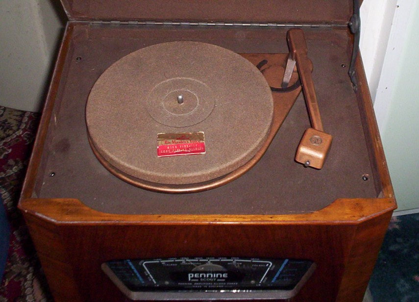
This wasn't a great problem as I'd no urge to play 78s and have better uses for the Gram input. The pick-up must have had quite a high output as modern devices seemed very quiet when connected; being a short superhet it has one less gain-stage so I set about devising one.
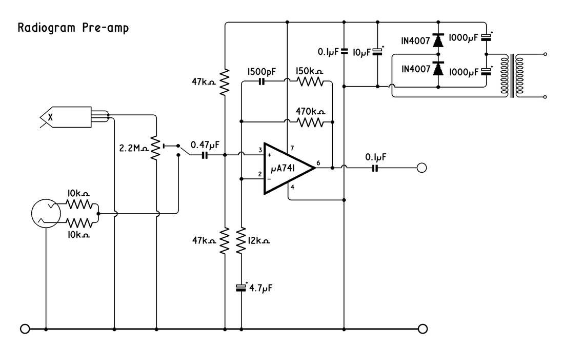
The obvious thing would be to bung another valve in but I'd no idea how much redundancy there was in the power supply and the last thing I wanted to do was overload the transformer. This left the option of a solid state device. And after some experimenting I settled on the attached circuit based around a µA741. This may well not be the best device available but I'd got some and they seem pretty free of vice and are well-documented. Besides that the design is now fifty years old which gives it a certain 'vintage' appeal — it bends the brain to think that the μA741 has been around for longer than the valves in the radiogram had when it came out.
I had intended powering this from the valves' LT supply as I couldn't see drawing a few extra milliamps from that being a problem. I hooked this up via four diodes configured as a bridge rectifier but two of them literally blew up as one side is earthed. I therefore fitted an additional transformer out of an old 'phone charger.
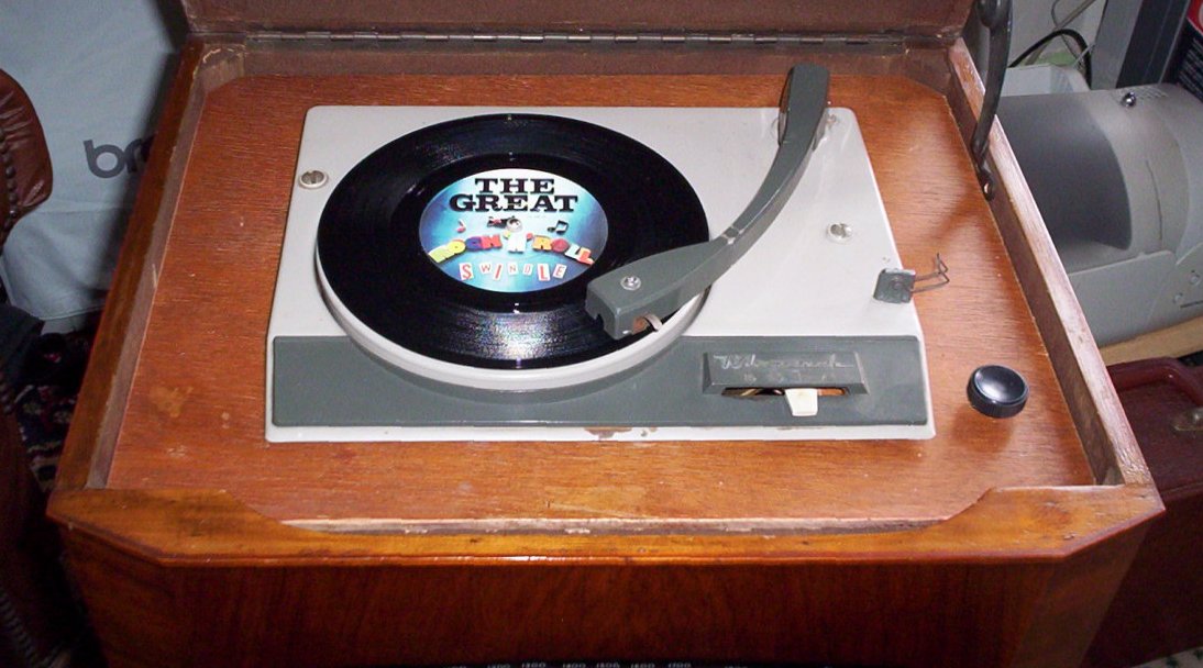
I had a spare record deck so thought I may as well fit that along with a "Gram/Aux" switch so I could still use it to play digital radio through.
Cosmetically there wasn't much to do beyond cleaning and polishing. The top of the lid was quite badly ridged and the lacquer cracked but a rub over with a pan-scrubber dipped in boiled linseed oil followed by beeswax greatly improved it. It certainly looks better than it would had I stripped and re-polished it as it would then look brand new.
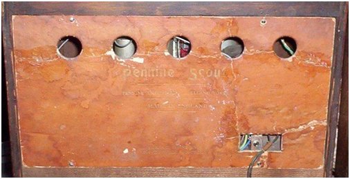
The biggest problem was the back. This was laid loose on the chassis and was flaking and had a crack right across it so that it was barely holding in one piece. My initial reaction was to make a new one but I then thought that there was nothing lost in trying to repair it.
I stuck down the loose bits with PVA glue and then ran some into the cracks before spraying the whole thing with water and running the iron over it on both sides. This treatment was far more successful than I'd dared to hope and no further reinforcing was needed.
As will be obvious, I didn't loose any sleep over worries about 'Authenticity' on this job not least because the modifications I've made could be completely reversed in a few minutes. Besides, the ends justify the means as it sounds fantastic and gets far more use than it would if it could only receive AM radio and play 78s.