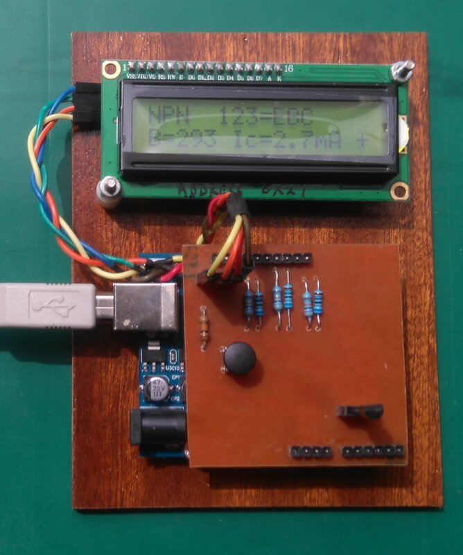
ArduTester
The Chinese devices sold as ‘Component Testers’ or ‘Transistor Testers’ are actually based on an open source project called the ArduTester. It is therefore quite possible to make your own, though as the bits would cost about the same as a ready-made one there’d be little point if you haven’t already got them.
Sadly, as with so much open-source stuff, documentation is a problem. It is further complicated in this case as the ArduTester has evolved over time and several versions exist. This is based on Version 1.13, which also seems to go by the names ArduTester More and ArduTester Millennium Edition. Details can be found here:
https://create.arduino.cc/projecthub/plouc68000/ardutester-millenium-the-ultimate-uno-mega-versions-c81db4
That is set-up to work with an Arduino Mega with an OLED 13x6 display connected via I2C. It can also work with a Uno and with different types of screen, or even the serial monitor.
After downloading the ZIP containing the code, either from the above link or the version below which is already set to use an UNO with 16x2 display, open it and extract the AduTester_more folder to your sketchbook.
Before trying to upload the code, open the file makefile.h and comment out/un-comment lines 8 to 11 to set the board type you wish to use. This version of ArduTester also has the ability to measure frequency but the UNO lacks the hardware for this to work so that needs to be disabled. The screen type is set by commenting out/un-commenting the appropriate blocks of code between lines 25 and 80.
You can now, hopefully, open ArduTester_more.ino and upload it to your Arduino.
The other circuitry can be built on a breadboard but I found it didn’t work very well — breadboards always seem to be a disaster area of bad connections, noise pick-up and stray capacitance. It does work very well on a PCB though. Details of both options are also in the ZIP below.
Before use it should be calibrated. The process takes several minutes so don’t panic if it seems to have hung-up. To do this press and hold the button until it displays:—
Selection:
Transistor
Now keep pressing the button until it says:--
Selection:
Selftest
Next connect all three test points together and press and hold the button until it says:--
short Probes!
It will now show gibberish until it says:—
isolate Probes!
At that point disconnect the test points from each other and wait until it displays:--
1-||-3 >100nF!
Connect a capacitor with a value between 100nF (0.1μF) and 20μF across Test Points 1 and 3.
Eventually the display will go back to:—
Eventually the display will go back to:—
Selection:
Selftest
You can now click through to:—
Selection:
Transistor
Then press and hold the button and normal operation should commence.
Here's the ZIP with modified code, diagrams and PCB details.
Here's the ZIP with modified code, diagrams and PCB details.

