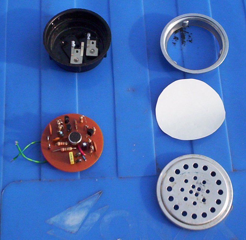
Microphones, correctly called "Transmitters," are a bit of a weak spot in old telephones. The Post Office regarded them as consumable parts as they wear out with use and also 'go off' in storage, especially if they've been damp.
Inside are carbon granules. As you speak the vibrations cause these to squeeze together lowering their electrical resistance. Over time these granules break up or stick together either causing crackles, low volume or sometimes they stop working completely.
In the late 1970s the GPO developed an electronic replacement, the Number 21A. These are easily available but the going rate is about £8. However, I came across details on making something that does the same thing.
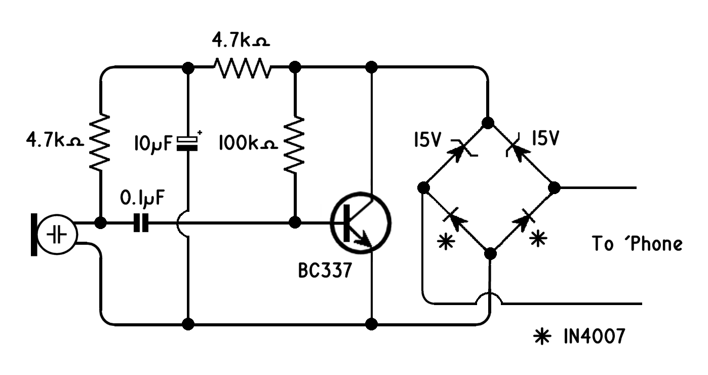
The design specifies some quite odd values of capacitor but I had no trouble substituting more common ones for these. I haven't got any BC639s either so used a BC337 — and found the hard way that the pin-out is different. I also used one for T1 and a BC327 for T2. It works very well (but see Update below) and cost well under a pound.
After making and testing, the PCB needs protecting against condensation. Either cover the top of the electrect with a bit of tape and then spray the whole board with lacquer or paint it with nail varnish.
I'd got a duff Number 16 Transmitter so took that to bits, turned the bottom off the aluminium casting and fitted the PCB in that. It would be perfectly possible to cut this off with a hacksaw or grind it away with a power sander. The anti-gob membrane is just a piece of thin plastic.
Inside are carbon granules. As you speak the vibrations cause these to squeeze together lowering their electrical resistance. Over time these granules break up or stick together either causing crackles, low volume or sometimes they stop working completely.
In the late 1970s the GPO developed an electronic replacement, the Number 21A. These are easily available but the going rate is about £8. However, I came across details on making something that does the same thing.
The design specifies some quite odd values of capacitor but I had no trouble substituting more common ones for these. I haven't got any BC639s either so used a BC337 — and found the hard way that the pin-out is different. I also used one for T1 and a BC327 for T2. It works very well (but see Update below) and cost well under a pound.
After making and testing, the PCB needs protecting against condensation. Either cover the top of the electrect with a bit of tape and then spray the whole board with lacquer or paint it with nail varnish.
I'd got a duff Number 16 Transmitter so took that to bits, turned the bottom off the aluminium casting and fitted the PCB in that. It would be perfectly possible to cut this off with a hacksaw or grind it away with a power sander. The anti-gob membrane is just a piece of thin plastic.
|
|
|
Number 21A transmitters are a drop-in replacement for the Number 16 that was used in plastic handsets from the 1960s to the 1980s but they won't physically fit in the old Bakelite Handset 164s, although they can be modified to.
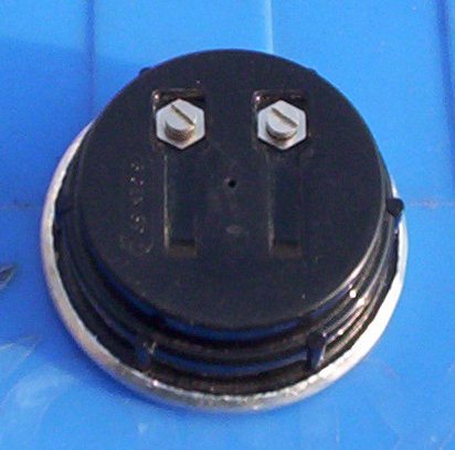
If the above circuit is used and a larger surround allowed 'round the PCB tracks it will fit inside a Handset 164 and can held it in place by turning over the forked connector which would normally press against the back of a carbon transmitter after well insulating the ends.
If the above circuit is used and a larger surround allowed 'round the PCB tracks it will fit inside a Handset 164 and can held it in place by turning over the forked connector which would normally press against the back of a carbon transmitter after well insulating the ends.
|
I cut a circle from some thin packing foam, which isn't dense enough to block sound, and put in the back of the mouthpiece as a spit guard and it also helps to stop the mouthpiece from rattling.
As well as the cost saving no original parts are removed, other than the transmitter, so the original configuration can be easily restored if subsequently desired. |
|
Update — May 2017
At the time I wrote the above I didn’t have a telephone landline. The ’phones I fitted these transmitters to were ones I was fixing up for a then friend who was an antique dealer. They passed the tests we subjected them to but when I did get a landline (which I didn’t really want but it’s cheaper to have one than just broadband) and used them in anger I found a problem: I was deafening myself.
Obviously the gain needed reducing but doing so was beyond my extremely limited knowledge of transistors. I did find that upping R3 from 4.7KΩ to 100kΩ helped but that seemed only slightly less crude than sticking insulation tape over the electrect.
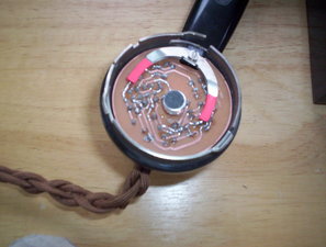
Looking on the internet revealed very few alternatives. There were two or three circuits that did the same thing with a single transistor but I found that these designs either didn’t work at all or not well enough to actually use. After taking ideas from several I came up with a configuration that does work.
I’d always thought that the three transistor circuit was needlessly complex and mine is much simpler; it’s simple enough to make ‘dead-bug’ style so it can be squeezed into things like Trimphones or even into old Transmitter No 13s making a drop-in replacement to use in a Handset 164. It can also be made on Veroboard if you don’t have facilities for making PCBs.
Here is a ZIP containing further details.
Here is a ZIP containing further details.
