Telephone Ringing
Detector
I’ve called this a ringing detector for want of a better name, and it certainly seems to be a widely used term for such things. A better description would be a relay that is operated by telephone ringing current.
I wanted a telephone bell that I could hear when I was outside, and particularly when I’m in a shed.
Exterior bells, both ‘Vintage’ and new are available but they need paying for and that is against my religion. I had got a 12V fire-bell which would be ideal if I could interface it to the telephone line.
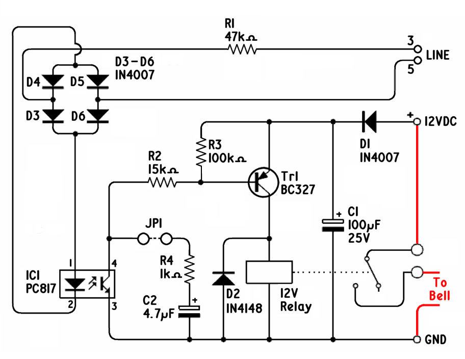
This is what I came up with, which didn’t cost me anything as they were all parts I’d got; IC1 came out of an old power supply:--
When JP1 is open the relay pulls in and drops out 25 times a second, which works best with my bell. With it linked C2 smoothes out the bumps so the relay stays in while ever the telephone is ringing.
The numbering of BT-style plugs and sockets is plain insane. The numbers on the diagram are those that would be found on the back of a socket. The plugs are numbered backwards though so that socket terminal 5 connects to plug terminal 2, 4 to 3, 3 to 4 and 5 to 2. Plugs are numbered starting at the side furthest from the lever and, to add to the fun, terminals 1 and 6 are usually not fitted. Therefore counting from the lever, and assuming the plug only has four contacts, this devise should be connected between the second and fourth contacts.
If you’re re-using an old cord these SHOULD be the blue and white wires. If it uses the American colours it will be green and black. It's best to check with a continuity tester or ohmmeter though.
If you need to use micro-filters with your telephones you'll also need one with this.
As well as ringing a bell it could be used to flash a light in noisy environments or if you listen to music with headphones so can’t hear a telephone ring.
If you want to use it to ring a small bell that doesn't need much current you can omit the relay and connect the bell straight across D2 and amend the supply voltage to suit.
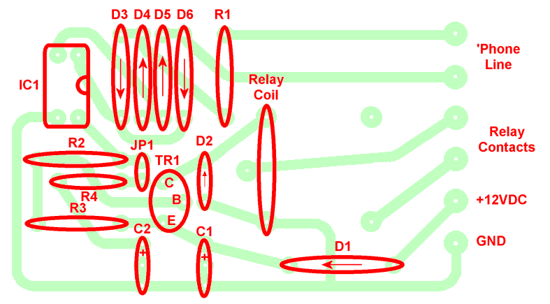
PCB Details:--
These images are available as PNG files in a ZIP here.


