
The LM317
LM317s are very useful linier voltage regulator ICs on which there is lots of information on-line but a lot of it fails to tell the whole story. A widely repeated misconception is that the output can only be set between 1.2V and 37V. This isn't in fact the case. The limiting factor is the difference between the input and output voltages. In other words they can't be closer than 1.2V or more than 37V apart. If you want 50V out you can do it providing the voltage going in is between 51.2V and 87V.
Lest it be thought that I'm talking through my arse here's a clip from the Motorola data-sheet:--
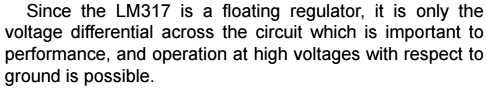
Just what the upper limit is is hard to determine: National Semiconductor simply say "... supplies of several hundred volts can be regulated as long as the maximum input to output differential is not exceeded, i.e., avoid short-circuiting the output."
The other thing that doesn't seem to be widely published is the formula for working out what to make R2 for a particular desired output voltage. It's all very good telling us the formula for Vout but it's not much good to we mathematical idiots who can't transpose it for R2. Here it is:--
The other thing that doesn't seem to be widely published is the formula for working out what to make R2 for a particular desired output voltage. It's all very good telling us the formula for Vout but it's not much good to we mathematical idiots who can't transpose it for R2. Here it is:--
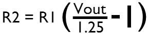
R1 is usually shown as 240Ω but doesn't need to be, it's certainly possible to use a more common E12 value like 220Ω or 270Ω. Frankly the easiest thing if you want less than 13V out is to use a 220Ω resistor for R1 and a 2.2kΩ preset for R2 and twiddle that 'til you get the output you want. You can use a bigger pre-set for higher voltages but doing so would make setting it fiddly for smaller ones.
A certain amount of current flows through R1 and R2 all the time so if you are working on a battery supply it makes sense to keep this as low as possible and 1kΩ for R1 will be OK. You have to be careful with very low current loads as if less than 10mA is flowing the regulator will stop working and the output voltage rise.
A certain amount of current flows through R1 and R2 all the time so if you are working on a battery supply it makes sense to keep this as low as possible and 1kΩ for R1 will be OK. You have to be careful with very low current loads as if less than 10mA is flowing the regulator will stop working and the output voltage rise.
