The LM386
LM386s are very useful, and cheap, audio amplifier ICs. They will work from a DC supply of between 5 and 15 volts making them very handy for use with batteries.
This is the simplest possible circuit using one:--
LM386s are very useful, and cheap, audio amplifier ICs. They will work from a DC supply of between 5 and 15 volts making them very handy for use with batteries.
This is the simplest possible circuit using one:--
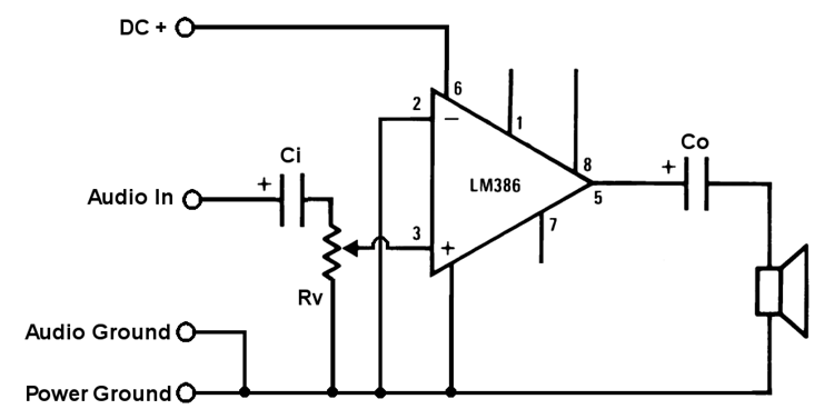
which is often all that is needed.
Rv is the volume control, usually 10KΩ.
Ci is the input capacitor. This blocks any DC that may be on the input from getting to the amplifier. 0.1µF to 1µF are usual values
Co is the output coupling capacitor which stops any DC from getting to the speaker. 220µF is the usual value.
Other refinements can be added as desired:--
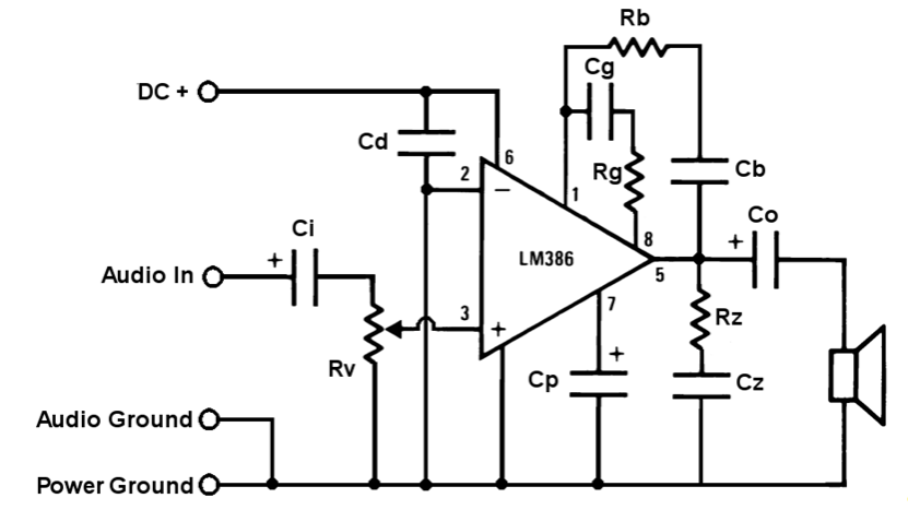
Rv, Ci and Co are the same as in the simple circuit.
Cd is a power decoupler which shorts out any high frequency interference that the power leads may have picked up. 0.1µF is the usual value. It's often beneficial to put a 100μF across the that as well, especially if it's been powered by a supply some distance away such as a wall-wart. It also helps to support a failing battery meaning more life can be squeezed out of it before changing it.
Cg and Rg set the gain. The simple circuit has a gain of 20. If a 10µF capacitor is fitted between pins 1 and 8 the gain will be 200. The Rg sets values in between — see below for details.
Cb and Rb (0.03µF and 10kΩ) form a bass boost which is useful for stopping small speakers from sounding tinny. The manufacturers call this a "Bass Boost" but in fact it reduces the treble meaning there's proportionally more bass.
Rz and Cz (10Ω and 0.047µF) form a Zobel network to prevent high frequency oscillations and instability, though I've never found them necessary.
Cp is a bypass capacitor which helps get rid of noise coming from poorly filtered power supplies. The value depends on how noisy the supply is. Try 10µF and if that doesn't work try 47µF.
The power output is dependant on the supply voltage and speaker impedance; the higher the supply and/or the lower the speaker impedance the higher the power.
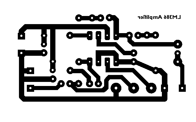
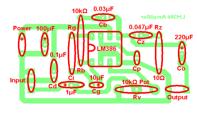
The following PCB design includes all possible components but the ones which aren't wanted can easily be omitted. Click the link at the bottom of this page to download it as a PNG file.
Cd is a power decoupler which shorts out any high frequency interference that the power leads may have picked up. 0.1µF is the usual value. It's often beneficial to put a 100μF across the that as well, especially if it's been powered by a supply some distance away such as a wall-wart. It also helps to support a failing battery meaning more life can be squeezed out of it before changing it.
Cg and Rg set the gain. The simple circuit has a gain of 20. If a 10µF capacitor is fitted between pins 1 and 8 the gain will be 200. The Rg sets values in between — see below for details.
Cb and Rb (0.03µF and 10kΩ) form a bass boost which is useful for stopping small speakers from sounding tinny. The manufacturers call this a "Bass Boost" but in fact it reduces the treble meaning there's proportionally more bass.
Rz and Cz (10Ω and 0.047µF) form a Zobel network to prevent high frequency oscillations and instability, though I've never found them necessary.
Cp is a bypass capacitor which helps get rid of noise coming from poorly filtered power supplies. The value depends on how noisy the supply is. Try 10µF and if that doesn't work try 47µF.
The power output is dependant on the supply voltage and speaker impedance; the higher the supply and/or the lower the speaker impedance the higher the power.
The following PCB design includes all possible components but the ones which aren't wanted can easily be omitted. Click the link at the bottom of this page to download it as a PNG file.
Gain Setting
I’ve left this ’til last as it’s horribly complicated and I didn’t want to scare anybody off.
To work out the value of Rg for a particular desired gain we need to look at what’s actually in the chip:--
I’ve left this ’til last as it’s horribly complicated and I didn’t want to scare anybody off.
To work out the value of Rg for a particular desired gain we need to look at what’s actually in the chip:--
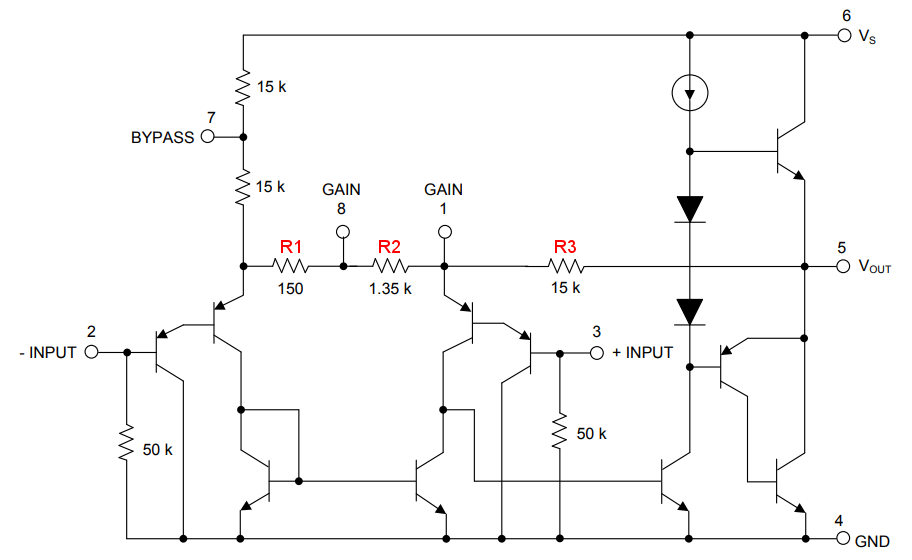
The gain is set by the ratio of R3 to the combined size of R1 and R2. Un-modified this is 15kΩ to 1.5kΩ which is 10. To find out the gain you double that and get 20. Now if we put a 10μF capacitor across R2 (Cg above) we short it out as far is AC is concerned. This means that R1 plus R2 is 150Ω which is a hundredth of R3 which doubled gives us a gain of 200.
So what if we want a gain of 100? The combination of R1 and R2 will need to be a fiftieth of R3, ie 300Ω. R1 is giving us 150Ω already so we need to make R2 150Ω but we can’t open the chip and change it. What we can do though is put a resistor is series with the 10μF cap (Rg above). Ideally this would be 168.75Ω but the nearest real-world value is 180Ω. So 180Ω in parallel with 1.35kΩ is 159Ω. Adding that to the 150Ω from R1 gives us 309Ω. 15kΩ divided by 309Ω = 48.5 so a gain of 97. If it HAS to be dead-on 100 you’d have to make up a more complex network of fixed resistors or use a pre-set.
Click here to download this as a PDF and the PCB artwork in PNG format.
