DAC90a Number Three
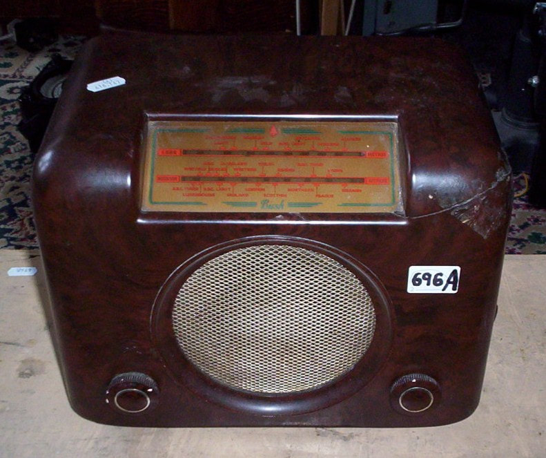
This was another local auction purchase. Despite already having two I wanted to do this as it had a broken case which would be an interesting change. It was also a later version than my others.
This was another local auction purchase. Despite already having two I wanted to do this as it had a broken case which would be an interesting change. It was also a later version than my others.
|
|
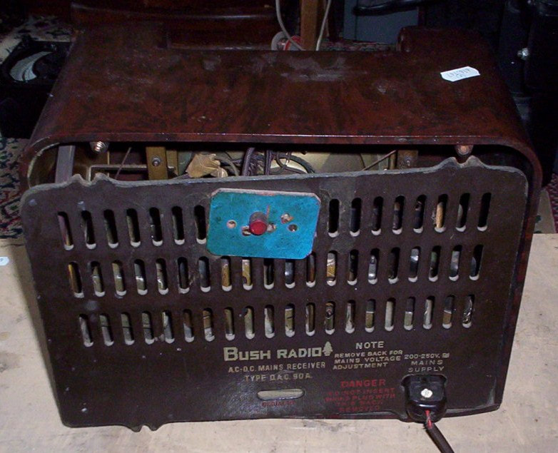
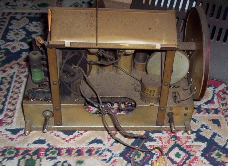
The wiring is in a bit of a state.
I took the chassis out and noticed that the voltage selector was on 210V. The top bit of the dropper looked very dark and I expected it to be o/c and then somebody had re-set the voltage selector to by-pass the damaged bit. It seemed OK so I put that up to 250V. I then changed the AF coupler and, after checking none of the balding wires were touching, gave it some juice. Nothing seemed to be happening but I then saw faint glows through the muck on the valves. I also saw that the lamp limiter was getting un- healthily bright. I then remembered that I hadn't snipped the filter. This looked like it had already spewed it's guts at some stage and after chopping its wire it played quite happily.
The extra sockets on the back weren't connected to anything. The speaker leads had been extended but it must have been done some time ago as they'd had time to go crispy.
The extra sockets on the back weren't connected to anything. The speaker leads had been extended but it must have been done some time ago as they'd had time to go crispy.
I tested the grid on the UL41 and found about quarter of a volt. I'd always used my DMM for that but the battery was flat. I didn't use my valve voltmeter as I wasn't sure as to the safety of using this on a live chassis. It was interesting to note how connecting the AVO caused a drop in volume and my little 2000 ohm/volt one an even greater one.
It certainly didn't seem to be working very well and I soon found that the HT was low. The fact it had been running on the wrong voltage setting could well have damaged the valves so I tried a different UY41 and that got the HT up nicely but it still didn't seem as good as my other DAC90as.
The main interest in this one was repairing the case. I was pleased to find that it hadn't been glued but stuck up with parcel tape so doing a better job was more straight-forward.
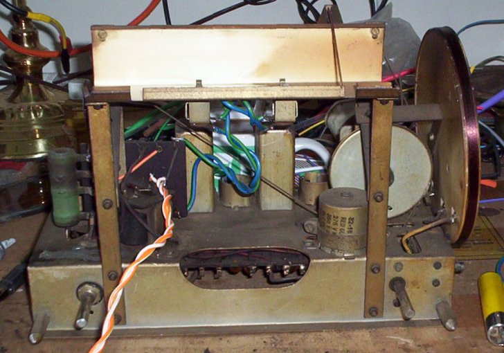
When I was dusting the worst of the muck off the aerial coil started to fall off the former so first thing was to put some shellac on that.
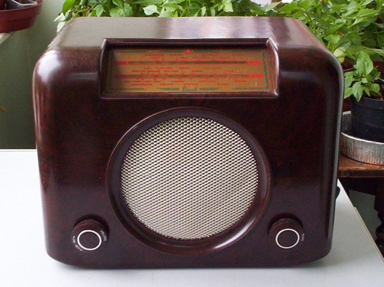
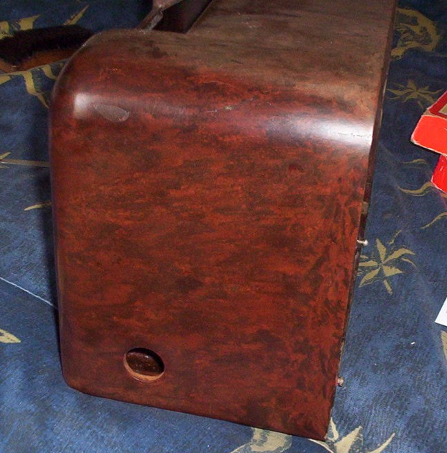
I then washed the case did the re-wiring. The photo shows the light-box half cleaned to show the contrast.
It certainly didn't seem to be working very well and I soon found that the HT was low. The fact it had been running on the wrong voltage setting could well have damaged the valves so I tried a different UY41 and that got the HT up nicely but it still didn't seem as good as my other DAC90as.
The main interest in this one was repairing the case. I was pleased to find that it hadn't been glued but stuck up with parcel tape so doing a better job was more straight-forward.
When I was dusting the worst of the muck off the aerial coil started to fall off the former so first thing was to put some shellac on that.
I then washed the case did the re-wiring. The photo shows the light-box half cleaned to show the contrast.
Following my early experiences I'd always changed all wax and/or Hunt's capacitors on sight. For once on this set I decided to gave the old caps the benefit of the doubt for a while; I'd no plans on selling it so if it went wrong in the future it won't be a problem.
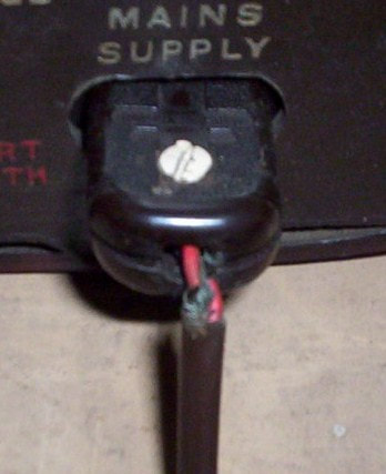
For the same reason it could keep it's deadly mains connector - if I were selling it I'd either hard-wire the flex or fit an IEC connector. The detachable things do have the advantage of making sure that it can't be jammed tight to a wall so it will always get some ventilation.
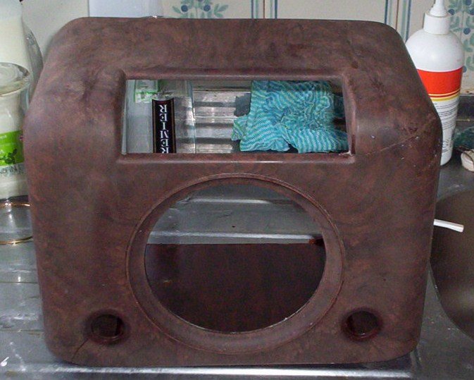
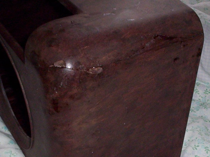
I gave the case a good wash and, as expected, it looked much worse afterwards.
For the same reason it could keep it's deadly mains connector - if I were selling it I'd either hard-wire the flex or fit an IEC connector. The detachable things do have the advantage of making sure that it can't be jammed tight to a wall so it will always get some ventilation.
I gave the case a good wash and, as expected, it looked much worse afterwards.
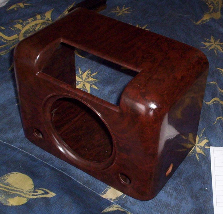
When it had properly dried I stuck it back together with epoxy and clamped it up while it cured.
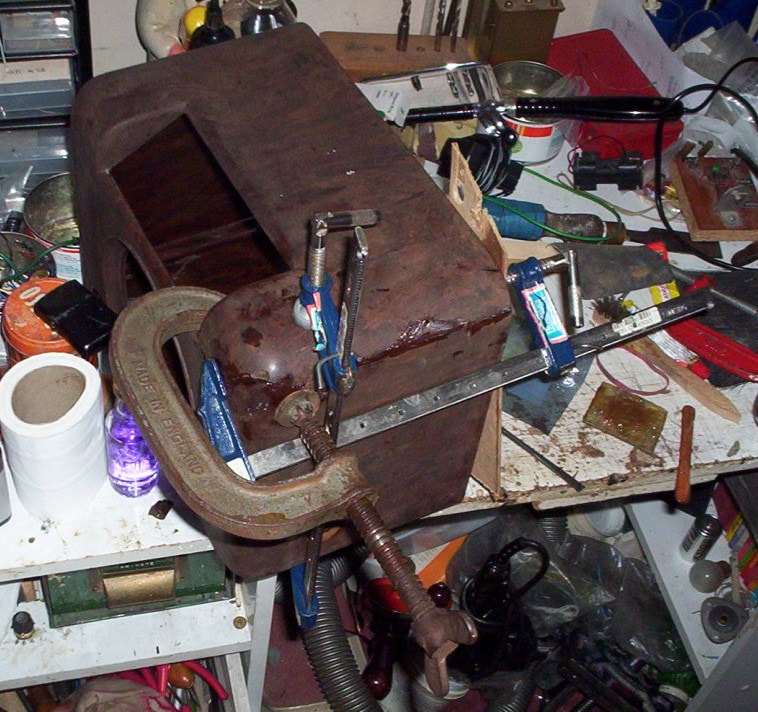
The next job was filling the chips.
I rubbed some wood on rough glass-paper, across the grain so the resulting dust was quite fibrous. I then stained that and left it to dry.
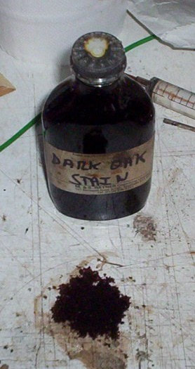
I then mixed that with epoxy and used this as a filler.
The colour-match wasn't great but I hoped it would improve with polishing.
The colour-match wasn't great but I hoped it would improve with polishing.
There was also a crack along the bottom edge but as this was out of site I only glued that and then gave it a good polish.
On the electronic front I changed the fixed tone corrector which, like the AF coupler was leaky but not too bad - the neon in my AVO bridge flashed whereas it usually on old caps it just lights up and stays on. The set seemed sensitive enough but wasn't very loud so I directed my enquiries toward the AF stages.
The RF bypass cap caused the AVO Bridge to flash like a strobe. Changing that improved the volume but it still seemed quiet.
I then screwed my courage up to the sticking plaster and tested the UL41 grid with the VVM. I couldn't see it doing any harm as that is isolated so should have been at no more risk of going bang than anything. This proved to be the case and there was over a volt on the grid so that got changed.
I still felt uneasy about having the old capacitors in place so checked the V2 and V3 cathode bypass cap and found these to be the leakiest to date.
I changed all the valves one at a time and, apart from the rectifier and output ones, and these swaps made no difference. It was certainly loud enough to use but not right. I had now concluded that I was spoiling the wireless for a quid's worth of caps so changed the rest.
Of the remaining five two were leaking badly, two were iffy and one may have been OK but wasn't perfect. My AVO Test Bridge only tests at 100V, and they were stone cold at the time so it really didn't seem worth the risk of leaving them. The proof of the pudding was in the eating as it made a huge difference to the sound quality and volume, in fact I'd say it's the best performing of the three DAC90as I have.
I also wanted to up the lamp shunt to make them brighter. The original was 75 ohms but was only reading 62 ohms.
I initially tried a 100 ohm one but this didn't seem to make much difference so I fitted a 180 ohm and that worked nicely. The early sets were fitted with 250 ohm ones so I was still well on the right side. The lamps are still dim but produce a friendly orange glow.
The other thing which is obviously 'wrong' with this set is the Perspex trims from around the knobs, which are a different type to the earlier versions, are missing. There's nothing remaining of them, not even old glue, but I prefer the look of the knobs without this adornment so will not be looking to replace them.